Design Plateability Analysis for turbine blades
An up-front plateability analysis on a blade or vane segment allows identifying the challenges that will have to be faced for plating recessed areas within minimal layer thickness spefiications and for ruling out high current density related layer quality problems around protruding edges and corners.

An up-front plateability analysis on a blade or vane segment allows identifying the challenges that will have to be faced for plating recessed areas within minimal layer thickness spefiications and for ruling out high current density related layer quality problems around protruding edges and corners. The only requirement for running a plateability analysis on a blade or vane segment is the availability of the CAD model of the part. Also the bath characteristics of the platinum plating bath that is operated by the customer need to be present in the PlatingMaster electrolyte database.

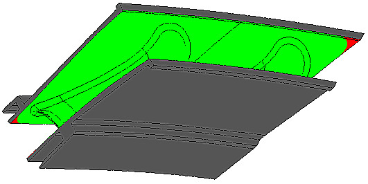
Typically a simulation for a plateability analysis runs with only the main tank anodes (at respectable distance) being active, and no other tooling components (current robbers, shields) being involved. Hence this analysis provides results for a worst case scenario. The simulated layer thickness distribution results for this double vane segment clearly show a huge problem with throwing power in the pathway in between both vanes. Also the deposit near the platform edges will suffer from poor quality due to the peak current density values that occur at these spots (red areas in picture below).

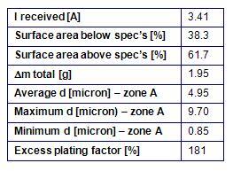
A plateability analysis will also provide general result data. A short overview is given in the table below.

For OEMs the results from a plateablity analysis on a blade or vane segment will yield valuable information on the lead time that suppliers will need in order to bring the part in production, and on the risk for potential warranty issues that might remain due to an insufficiently engineered plating process.
For suppliers to the OEMs a plateablity analysis will bring crucial information in the quoting phase, enabling to estimate the platinum consumption per part that will be needed to meet minimum layer thickness specs, and the required lead time and number of of trial and error runs for engineering and building a sufficiently elaborate plating tooling system.
